Turbine Blades
Per drawingThe drawing defines the datums and fit criteria for turbine blades; inspection scope is agreed for the project.
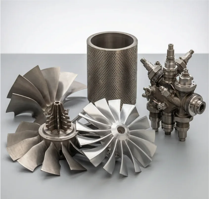
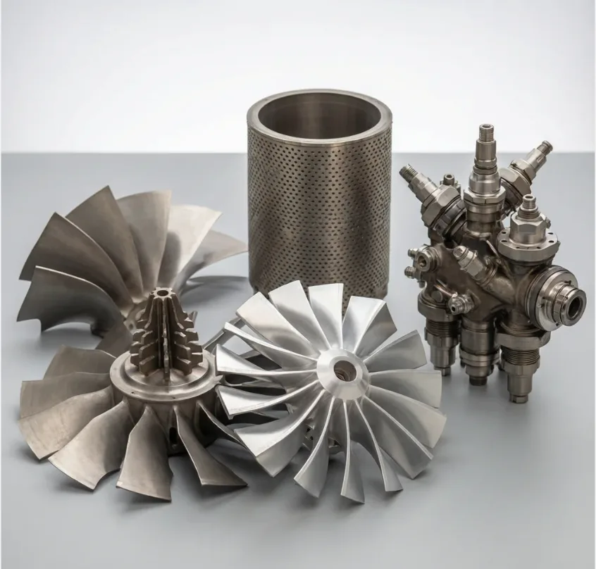
This aerospace propulsion case follows a complex rotating component from drawing interpretation through toolpath planning and inspection. The focus is access to blade passages, hub features and concentric interfaces in demanding aerospace propulsion systems.
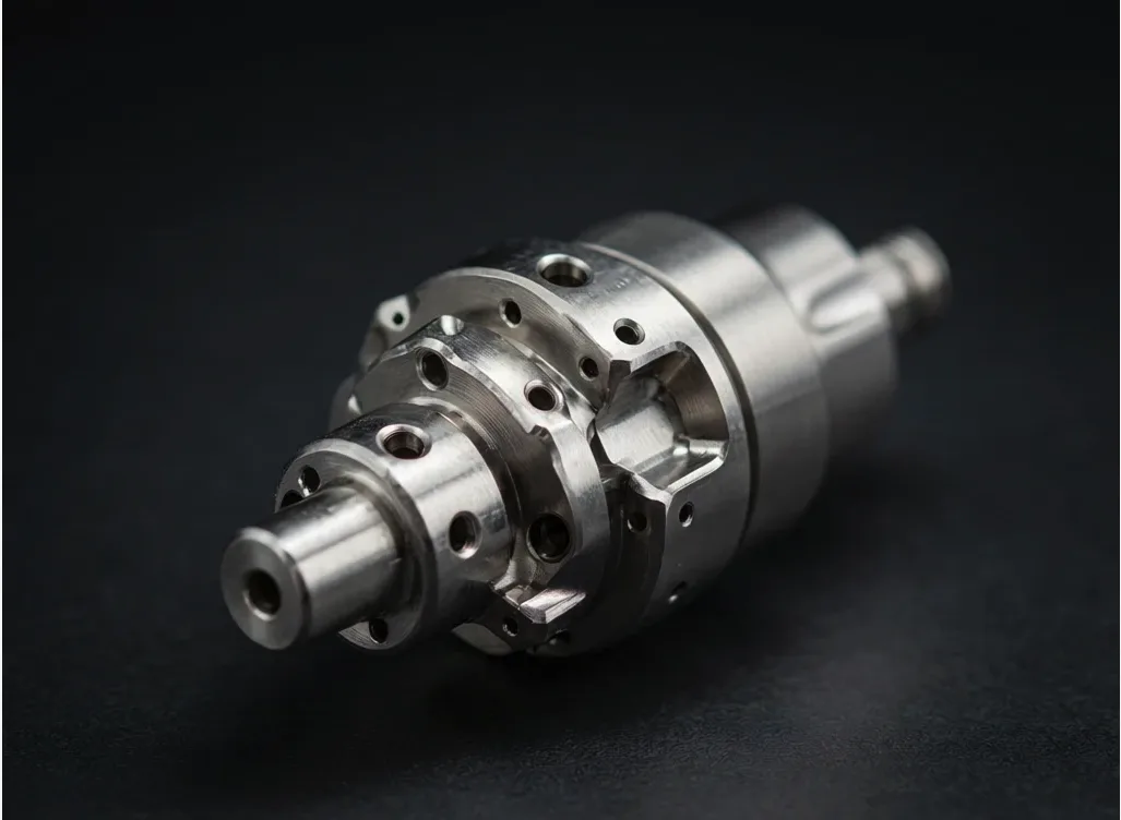
The case uses a monoblock impeller to show how aerospace propulsion systems turn a compact drawing into a sequence of accessible machining features. Blade passages, the hub bore and mounting interfaces must be considered together because each affects setup, cutting strategy and final inspection.
For a CNC machined impeller, the process plan separates roughing from finishing and protects the critical interfaces as material is removed. Aerospace turbine blades are reviewed in the same way: tool access, workholding and drawing-defined checks are settled before production parameters are committed.
From forged blank to flight-ready component
Inspection method, acceptance criteria, and requested records are agreed for the part and project scope.
Finite element analysis optimizes cutting parameters. Impeller Expert Modules automate toolpath generation.
High-speed roughing on GROB-class centers with through-spindle coolant. Layered strategy minimizes blade deformation.
We review semi-finishing and finishing operations against the drawing to confirm process fit and inspection scope.
Aging and cryogenic stabilization release stresses. EDM creates locking slots and precision features.
Click any component to request a detailed manufacturing quote โ each design below reflects current aerospace propulsion technology requirements.
The drawing defines the datums and fit criteria for turbine blades; inspection scope is agreed for the project.
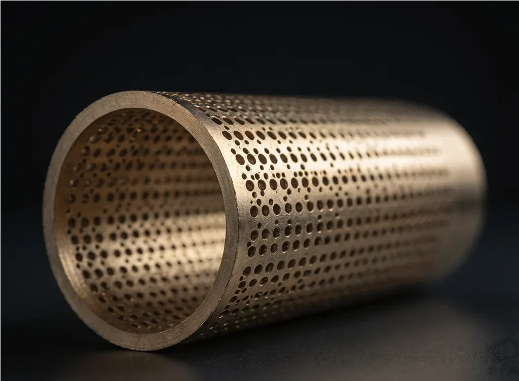
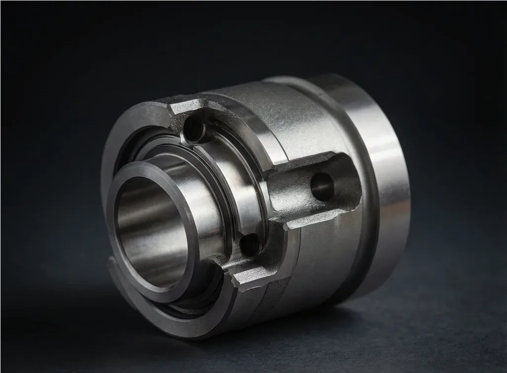
We review combustor liners against the drawing to confirm process fit and inspection scope.
We review fuel nozzles & injectors against the drawing to confirm process fit and inspection scope.
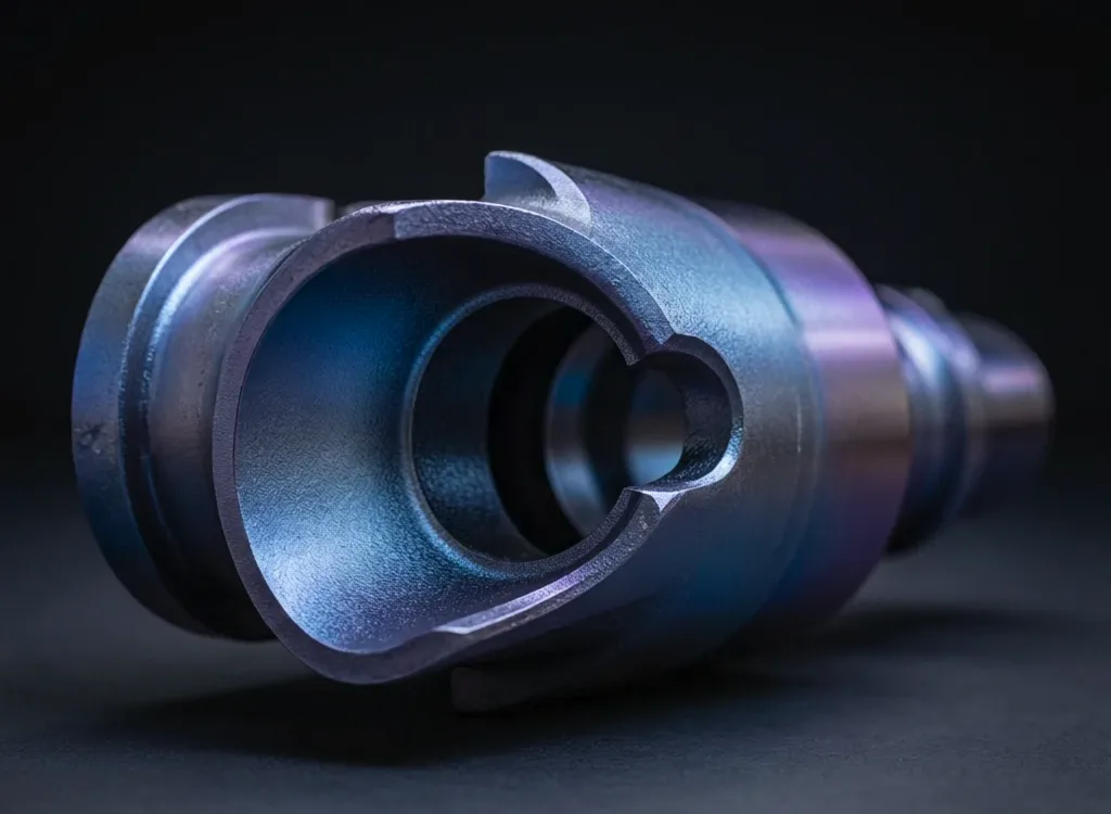
We review high-temperature alloy parts against the drawing to confirm process fit and inspection scope.
| Feature | Recommended | Why it matters |
|---|---|---|
| Min. wall thickness | As specified in the drawing / agreed scope | Below this, chatter and thermal distortion make Per drawing impossible to hold |
| Internal corner radii | As specified in the drawing / agreed scope | Small radii force fragile micro-tools and dramatically raise scrap risk |
| Draft angle (airfoil) | As specified in the drawing / agreed scope | Improves chip evacuation and reduces re-cutting heat buildup |
| Roughing allowance | As specified in the drawing / agreed scope | Leaves consistent material for stress-relieved final passes |
| Thin ribs / seals | As specified in the drawing / agreed scope | Prevents vibration-induced waviness on sealing surfaces |
Share the drawing through an agreed channel after initial contact. DFM questions and review timing are confirmed for the project.
We review deformation control: before vs. after dfm review against the drawing to confirm process fit and inspection scope.
The manufacturing review compares tool access, workholding, material removal and inspection requirements. Any process change or expected performance benefit is confirmed against the part drawing and validated project data.
Get Free Machining Simulation โQuotation timing is two business days after complete drawings and project requirements are received. Manufacturing lead time is confirmed for the specific material, process, finish and quantity.
Start Rapid Prototype โ
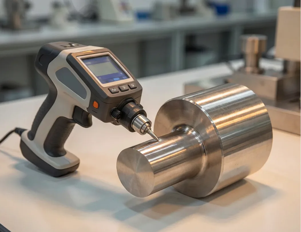
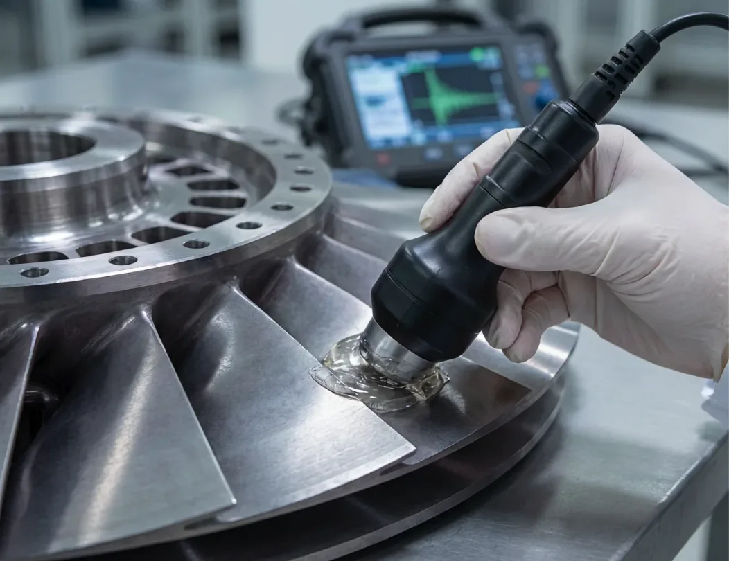
Internal defect detection ensures zero-flaw material before machining begins.
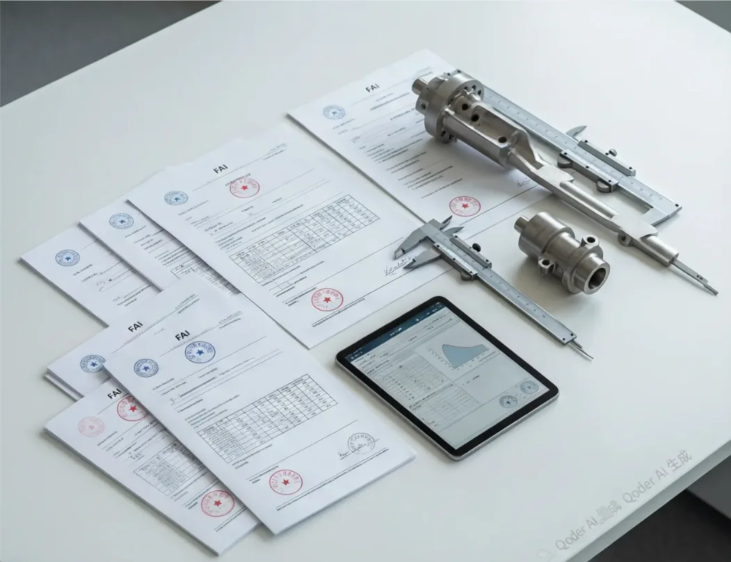
Certification, customer documentation, and special-process requirements are reviewed for each inquiry. Any applicable records and requirements are confirmed before quotation.
Material grade is considered against part function, operating conditions, and drawing requirements. Availability, finish options, and any requested material records are confirmed during quotation.
The part geometry, material, feature access, and quantity determine the suitable machining route. Feasibility and inspection scope are reviewed from the drawing before quotation.
Finish options are reviewed against the material, operating environment, and drawing. Availability, acceptance criteria, and any external processing are confirmed in the project scope.
Tolerance and fit requirements are reviewed against the supplied drawing. Feasibility depends on geometry, material, machining process, and agreed inspection scope.
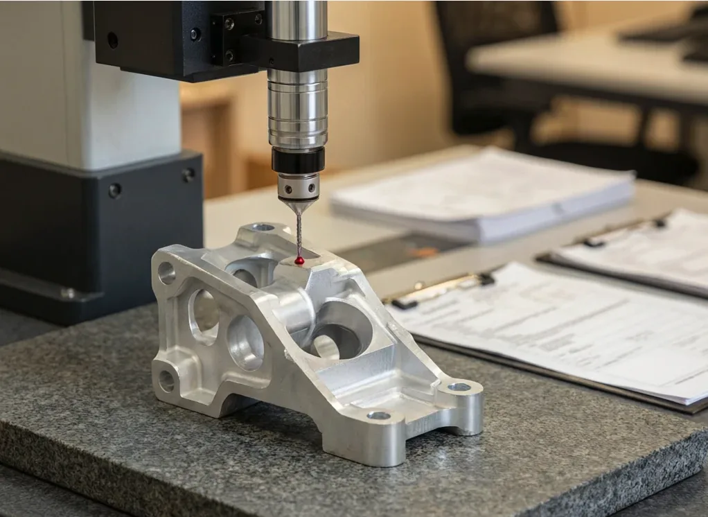
Inspection methods, acceptance criteria, and requested records are reviewed against the specification and included only when agreed in the project quotation.
Manufacturing lead time is confirmed after reviewing material availability, machining process, finish, and quantity. Quotation timing is two business days after complete drawings and requirements are received.
Requested quantity and production stages are reviewed against the part geometry, material, and process. Capacity and manufacturing lead time are confirmed for the agreed project scope.
Requests are reviewed from available samples, drawings, or CAD data. Required outputs, fit criteria, inspection records, and project scope are confirmed before quotation.
Quotation timing is two business days after complete drawings and project requirements are received. Manufacturing lead time is confirmed for the specific material, process, finish and quantity.
Submit a Project Inquiry โ